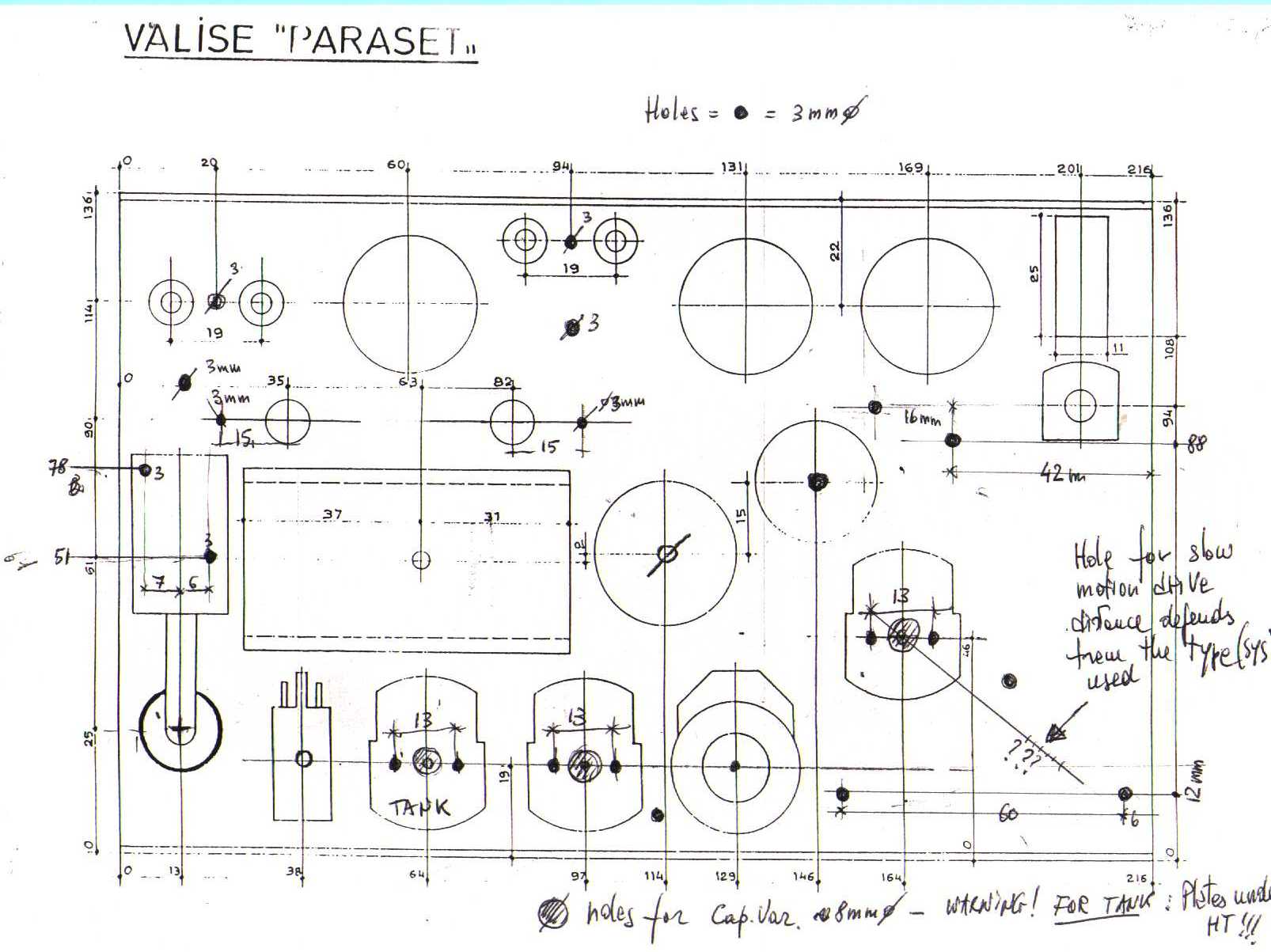
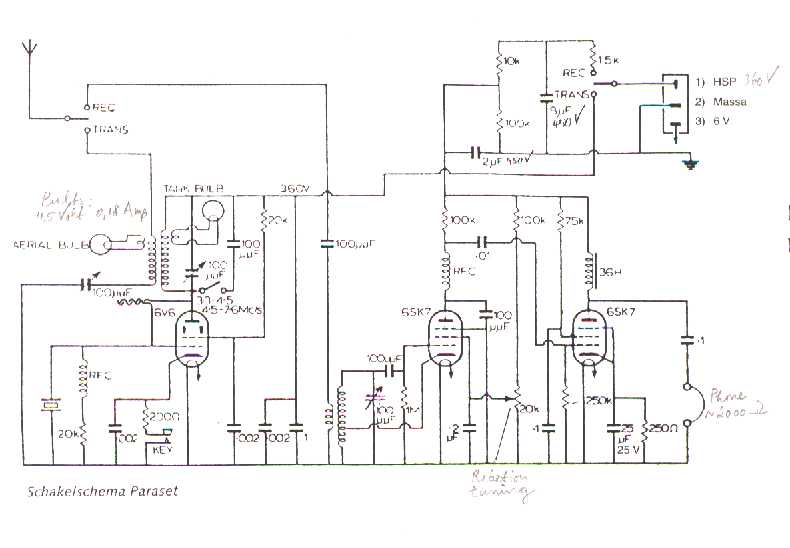
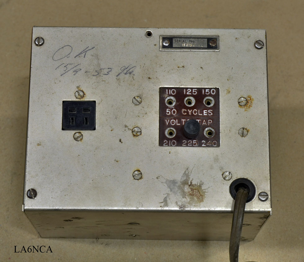
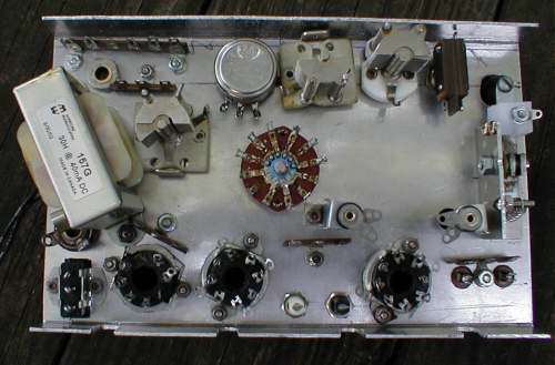
Paraset Radio Power Supply

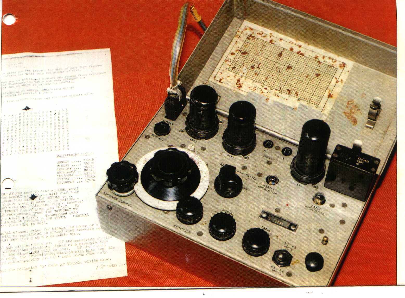
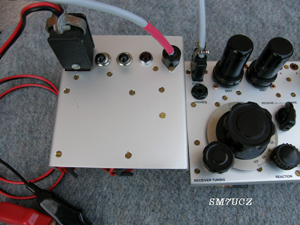
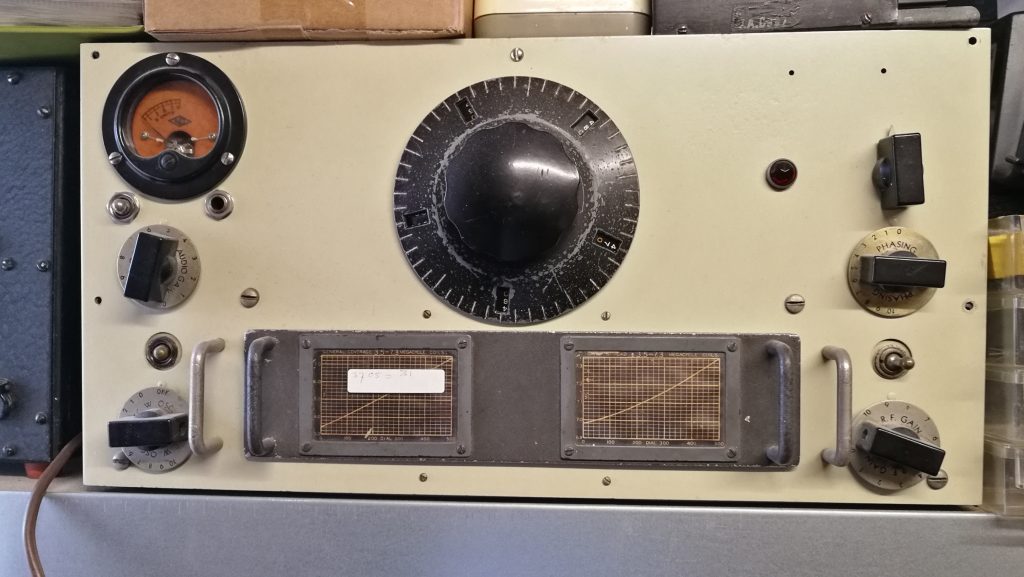
The Paraset Spy Radio With A Regenerative Receiver Covered 3 0 Mhz 7 6m Mhz In One Band The Output Power Was Approximately 4 5 Watts

Pin On Radios Boatanchors Antennas
Paraset Ita

Paraset 1942 Replica Spy Radio Receiving On The 80m Ham Band Youtube
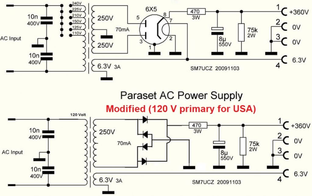
Power Supply For Mk Vii Www Paraset Nl
The Paraset Project Norwegian Style
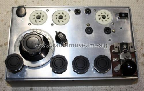
With a 12v6 the output was nearly 4 5w 50ma and 1 8a from battery.
Paraset radio power supply.
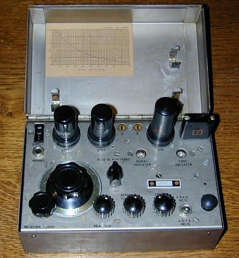
Radio Set Mk Vii Paraset
The Whaddon Mk Vii Paraset Tranceiver

Epingle Sur World War 2 Ground Military Systems Allies And Neutrals

Paraset Replica Transceiver Power Supply Connector The Original Idea Ebay
G3zps Web Pages
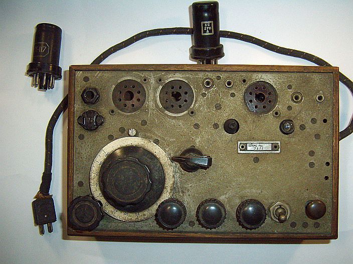
Mk Vii 2571 Ronval Set Www Paraset Nl All About Building Replicas Of Spy Radios

The Paraset Was One Of The First Successful Miniaturized Radio Sets For Britain S Special Operations Executive Which Cond Antique Radio Ham Radio Vintage Radio

Paraset Ww2 Spy Radio Soe By Martin Ward

Pin On Ham Radio

Pin On Spy Shortwave Radio Wwii

Kr7w S Ham Radio Blog November Qrp Tech Challenge Build Ww2 Paraset Spy Radio Part 1
Whaddon Radio Set Mk Vii Paraset Commercial Trx Military U
Parasecond
Paraset The Radioboard Forums

Soviet R 104m Divisional Regimental Radio Radioamatori Radio Militari

The Secret British Organisation Of The Second World War 3d Printed Metal War World War
Paraset Soe Ww2

M0nde Paraset Enclosure

Pin On Ham Radio

Pin On Cb Radio

Wwii B2 British Spy Radio Wwii Radio Special Operations Executive
Paraset
Hut 22 Hro M Www Paraset Nl All About Building Replicas Of Spy Radios

Pin On Radio Porn
Source : pinterest.com
